Jan 16 2017 - Clear easy-to-read wiring diagrams and instructions for household circuit breakers including. By connecting a.
 New Doorbell Button Wiring Diagram Diagram Diagramsample Diagramtemplate Wiringdiagram Diagramchart Worksheet Doorbell Doorbell Transformer Boat Battery
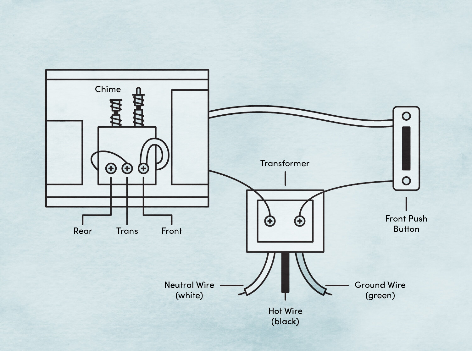
Doorbell transformers often have two screw terminals.
Amp wiring diagram chime. A breaker panel box 15amp 20amp 30amp 50amp and gfci breakers. For top-mounted battery posts the most common way to do this is to crimp a ring terminal onto the end of the. Typically the ground wire will be green the neutral wire will be white and the hot or live.
Chime Amp The Chime Amp is a 1 watt practice amp based on the punch amp. These three wires connect the doorbell transformer to your homes electrical system. Connect the diode to the terminals pointing towards the chime as shown in the diagram.
Mono Amplifier Wiring Configurations The impedance listings in the above diagrams are for reference only. I just hooked up an Alpine mini 4 channel amp to my factory radio and now the chime and turn signal are beyond too loud. Wiring a 20-Amp 240-Volt Appliance Receptacle.
Page 50 18 PIN CONNECTOR AR-CH2 T-HARNESS AMP TURN ON NC. Check out our amplifier wiring diagram to see how the wiring gets connected in a typical 2-amp system. Models IA-28 or IA-29 chime modules cannot be used CAUTION.
Wiring Diagram - CONNECT THE WHITE WIRE FROM ADAPTER TO RED WIRE. In the below diagram there are four possible wiring combinations having the same result. This outlet is commonly used for a heavy load such as a large air conditioner.
Connect the input wires on the transformer to the source circuit using the black to black white to white and ground to green method. Use of wire other than NuTone specified will cause improper operation. This wiring diagram shows how a full-blown car audio system upgrade gets wired in a car.
The tone from the amp is flat. Ground Neutral Hot Wires. Kenwood amplifier PROGRAMMED FIRMWARE ADS-AR-FOR02 PRODUCTS REQUIRED.
Ive read just about everything that I can find with a google search and no one has a clear solution. Attach the power cable to the positive battery terminal not directly to the battery post itself. Connect the PurpleBlack wire to the radios right rear negative speaker output.
One of these terminals connects via wire to the doorbell chime and the other connects to the doorbell push button. DATA CABLE SECOND AMP STEP 4 CONNECT THE BLUE WIRE PIN 16 MAESTRO AR MODULE TO SECOND AMPLIFIER IF PRESENT. Doorbell Chime Transformer AC IN Doorbell Wiring Diagram Note.
The system includes a 4-channel amp for the front and rear pairs of full-range speakers and a mono amp for a subwoofer. Wiring Diagram 5 Vehicle Wire Reference Chart 6. I recommend adding an EQ pedal or treble booster in front of the.
Connect the BlueWhite wire to the radios amp turn on wire this wire must be connected to hear sound from the factory amplifier. What Im going to try is switching the amp to 2 channel and getting the sign. GMOS-04 3 Connections to be made Connect the Purple wire to the radios right rear positive speaker output.
Add a doorbell chime to your shop or garage by connecting to either the existing chime or the transformerthe choice depends on how and where you run the wiring. A dual amplifier wiring kit. Wiring for a doorbell transformer and two buttons.
30VA Doorbell transformer httpamznto2woz5SVTo hook up a second doorbell in the basement backyard or garage you will need to make sure the transformer. Page 2 This is the primary application. The outlet should be wired to a dedicated 20-amp240-volt circuit breaker in the service panel using 122 awg cable.
The extra gear youll need for wiring the amps includes. The sounding device that produces a ring or chime or other type of sound when someone pushes the doorbell button. No other wire should be used.
If connecting to an electric chime a rectifying diode may be needed. With this wiring both the black and white wires are used to carry 120 volts each and the white wire is wrapped with electrical tape to label it hot. The system depicted includes new speakers an aftermarket receiver a 4-channel amp for the front and rear pairs of full-range speakers and a mono amp for a subwoofer.
Wiring Diagram for a Two Chime Doorbell. This project is a very simple and can be used to drive a speaker or headphones the chip will sense when headphones are connected automatically. When attaching the new chime at the transformer connect the new wires to the same wires and screws that the wires from the old chime.
Page 1 WIRING INFORMATION intercom speakers. Activate any chime ex. Your unaltered guitar signal.
Wiring for two doors is the same as for one with the transformerDoorbell RingerChime. Click on your setup to view the diagrams. CHIME ADJUSTMENT Chime volume adjustment will only work if the chimes are played by the vehicle speakers some Ford vehicles.
This system is designed to be used with NuTone with the IMA-516. Wiring Diagrams for Ring Video Doorbell Setup If youre in the process of setting up multiple Ring Video Doorbells internal doorbells and transformers the following wiring diagrams may help. Adjust the chime volume using the volume knob.
How to add an amplifier to your car audio system This simplified diagram shows how a full-blown car audio system upgrade gets wired in a car. Wiring Diagram for a Two Chime Doorbell Wiring for two doors is the same as for one with the transformer hardwired to the 120 volt source from a house circuit. Step 5 Connect the power wire.
They each provide the amplifier with a Mono 2-Ohm woofer load.
 Doorbell Wiring Diagrams Diy House Help Doorbell Transformer Doorbell Diagram
 Diagramsample Diagramformats Diagramtemplate Check More At Https Diagramspros Com Simple Contactor Wiring Diagram Bar Lighting Dimmer Switch Diagram
 15 Motorcycle Light Diagram Motorcycle Diagram Wiringg Net Motorcycle Wiring Motorcycle Lights Motorcycle Headlight
 Nutone Clock Door Chime Wiring Diagram Gallery Car Drawing Easy Diagram Ferrari Dealership
 Intercom System Wiring Diagram Intercom Diagram Electrical Diagram
0 Comments